Understanding, Maintaining and Troubleshooting ControlLogix Systems —with The Studio 5000 Designer Software
Keywords: ControlLogix, ControlLogix training, PLC, Programmable Controllers, Allen-Bradley training, Rockwell Training, controls, controllogix systems, buy controlLogix course, enroll in controlLogix training, get studio 5000 designer course, purchase troubleshooting controlLogix systems, control systems, controllogix control systems
Understanding, Maintaining and Troubleshooting ControlLogix Systems —with The Studio 5000 Designer Software
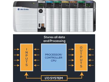
This module introduces you to the ControlLogix programmable controller from Rockwell Automation and you will thoroughly understand the integrated architecture of this wonderful product. In this first module we are going to jump in and cover some basics of standard PLCs including operation and functionality and how standard PLCs differ slightly from the ControlLogix platform.
We will also cover the fundamentals of number systems which provide the basis for digital control systems. Then, we will move to the understanding of logic and binary concepts which are used as the foundation of not only PLCs, but also of computers in general
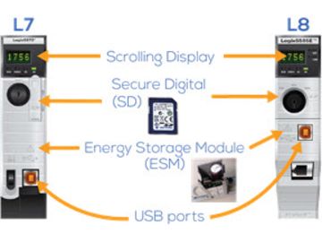
In the second module of the program, the ControlLogix hardware composition is covered which is critical to the understanding of the installation, configuration and troubleshooting of a ControlLogix system.
The hardware composition defines the architecture of the ControlLogix, the placement of the Input and Output (I/O) modules, and as we will see, defines the “addresses” of the field devices that will be connected to the input and output modules. The different Logix controllers (L7 & L8) are covered along with power supply, chassis, and I/O and communication modules not only for “Local” chassis but also for Remote I/O subsystems
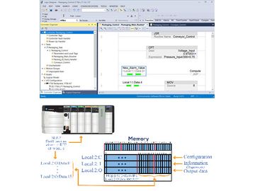
In this module of the program, a ControlLogix project is created in order to explore the Studio 5000 by navigating through the different sections of this powerful software. Also cover in detail is the functionality of the toolbars in the software which assist while troubleshooting.
Furthermore, I/O modules are added to the project and explore the relationship of the I/O field devices connected to the I/O system and their “tag” representation in the controller. This important navigation of the Studio 5000 software will be invaluable during its use when troubleshooting a ControlLogix system.
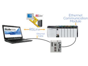
This module covers how to establish communication with the ControlLogix processor in a chassis via the Ethernet communications network. The course shows how via RSLinx, Allen Bradley’s communication software, different types of drives can be created to communicate in the network and what precautions we have to take during the driver creation. Important information is covered about networks which is necessary to know during troubleshooting of a project. Establish organization on IP addresses and how they can be assigned and managed to avoid confusion.
The Downloading, going Online and Uploading of projects is thoroughly covered and as well as things that users must be aware when doing these procedures. In depth detail about the controller’s operating modes is covered as well as how we go about during troubleshooting to monitor the status of tags for both discrete and analog field devices (analog scaled and non-scaled).
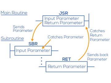
This module covers the project organization of a ControlLogix and also some of the frequently used structures that programmers use when creating code and that we are likely to encounter during troubleshooting.
The organization of the project by the controller is very important because it tells us where everything is stored and located. In this section we will focus more where the code resides because that is where most of the troubleshooting occurs and the understanding of this project organization is critical and essential.
The frequently used structures involve the use of Subroutines and the instructions used to properly execute the code residing in the Subroutine. We will point out to some important situations that we can confront during troubleshooting.
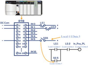
This module goes over ladder logic diagrams interpretation and covers the function of ladder instructions, information that must be mastered during troubleshooting. Coverage of not only the “basic” ladder instructions, but also some of the frequently used instructions which are likely to be encountered during troubleshooting. Although some of the basic instructions have been covered, important “things to look for” are presented when using these instructions during troubleshooting.
This module presents the use of a trapping “Gotcha” method to detect very fast ladder diagram responses that we will not be able to see under the monitoring of the logic. These Gotcha situations are very handy during troubleshooting. The programming of a normally closed input device is also presented—that is how to program a wired normally-closed input field device to behave like a normally closed, specially in fail-safe situations. Frequently used instructions that employ tag structures that we are bound to encounter when we are troubleshooting a system are thoroughly covered— an understanding of these tag structures is very important. These include timers, counters, math, compare. Additionally we will also apply the use of program control instructions during troubleshooting.
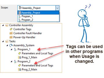
This module goes over the two types of “tag scopes” which are Controller or Global and Local or Program-scope. The understanding of these tag usages is very important when we are troubleshooting code and the state of tags in a ControlLogix. We will cover all the properties of Local or Program-scope tags and how we can change the “parameter usage” in order for the tags to be used in other programs.
Tag monitoring and editing is covered extensively since use these techniques extensively during the troubleshooting of a system and the topics presented are an invaluable resource needed to properly address system problems. The monitoring and editing if signals is presented for both discrete and analog systems. Editing online during troubleshooting is covered in detail to identify and modify field device’s wiring, code and test operational status using the Studio 5000 software.
Presented in detail is how to make changes to code if it is necessary to satisfy certain production requirements and how to properly document changes made. Arrays and User-defined Data Types (UDTs) are thoroughly discussed and examples are presented for troubleshooting potential problems that can shutdown the system
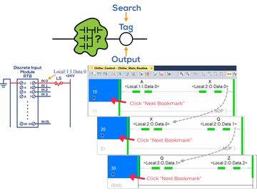
This module covers some of the best software tools available for troubleshooting ControlLogix systems. The Studio 5000 software, in addition to be used for programming and documenting a system, also has some magnificent tools that are used for troubleshooting a project. These tools include under Search, the Find, Find and Replace, Go To, Browse Logic and Cross Reference. These tools are also complemented by the Bookmark Toolbar capabilities. Additionally, this module also goes over some Program Control instructions that are mostly used in troubleshooting to by-pass testing sections rather than as code to alter the control flow of a Routine.
Also presented are several important situations that we must be aware when using Program Control instructions over other instructions in the code. Also explored are other ControlLogix tools used during troubleshooting that helps us get the system back online and find the solution to problems. These tools include the Forcing and Toggling functions used with I/O devices and internals.
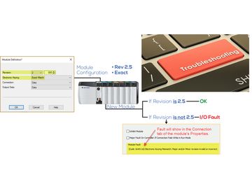
In this module, the troubleshooting of the hardware components that make up a ControlLogix system is thoroughly covered. These components include the discrete and analog I/O modules and in both of these cases we will also look at the important configurations of the modules to achieve proper operation.
In order to properly troubleshoot the discrete and analog I/O modules it is a good idea to understand in more detail the operation of the modules themselves. This involves how the communication between the processor and the I/O modules takes place and some common communication problems that are applicable to all modules. This section of the training program also covers in depth the communication between modules and controller which is necessary for the understanding of the asynchronous operation of the ControlLogix.
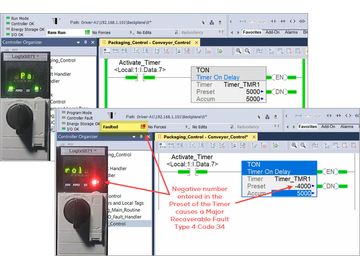
This module continues to troubleshoot the ControlLogix system hardware components like the Controller itself, the Power Supply and Remote I/O Subsystems. Starts with Remote Subsystems and finding out what can go wrong in the communications with the controller in terms of communications modules, wiring and network switching and solving possible network interference.
Discussions in detail about controller faults are covered as well as how to recover from these faults. And just in case we are faced during troubleshooting, we will also go over how the Fault Routines work and what we need to look for if when a fault is detected. Not just your basic Power Supply problems are covered but also how to prevent possible loading problems during normal operation thus avoiding system shutdowns.
Also we cover the important topic of how to deal with Noise and Heat problems when they occur as well as how to prevent them in the first place. This module finishes by taking an indepth look at two useful tools that can be used during troubleshooting which are the “Trend” tool, used for Trending tags or signals like a histogram, and the “Compare” which compares two ControlLogix projects to determine differences.
